
For my first official blog post, I felt it fitting to start from the beginning. Since BSides Edinburgh, a couple of weeks back, a few people have asked for some guidance on how to actually make use of the badges, and business PCB cards. Well, ask and ye’ shall receive!
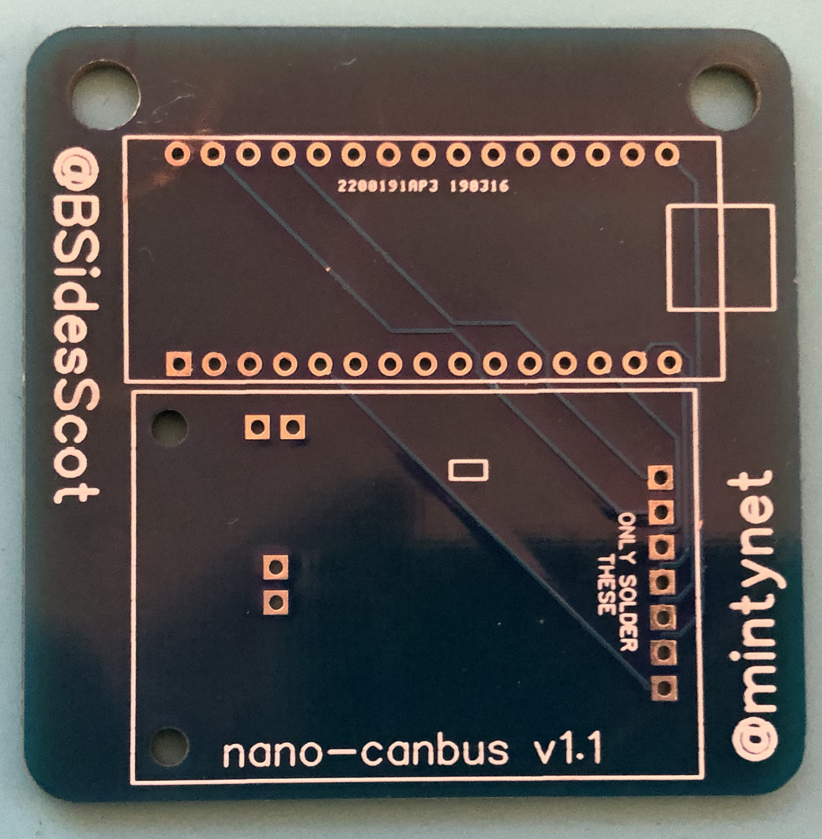
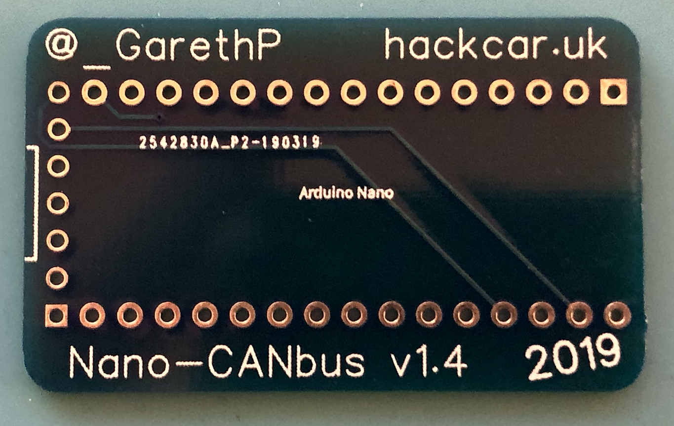
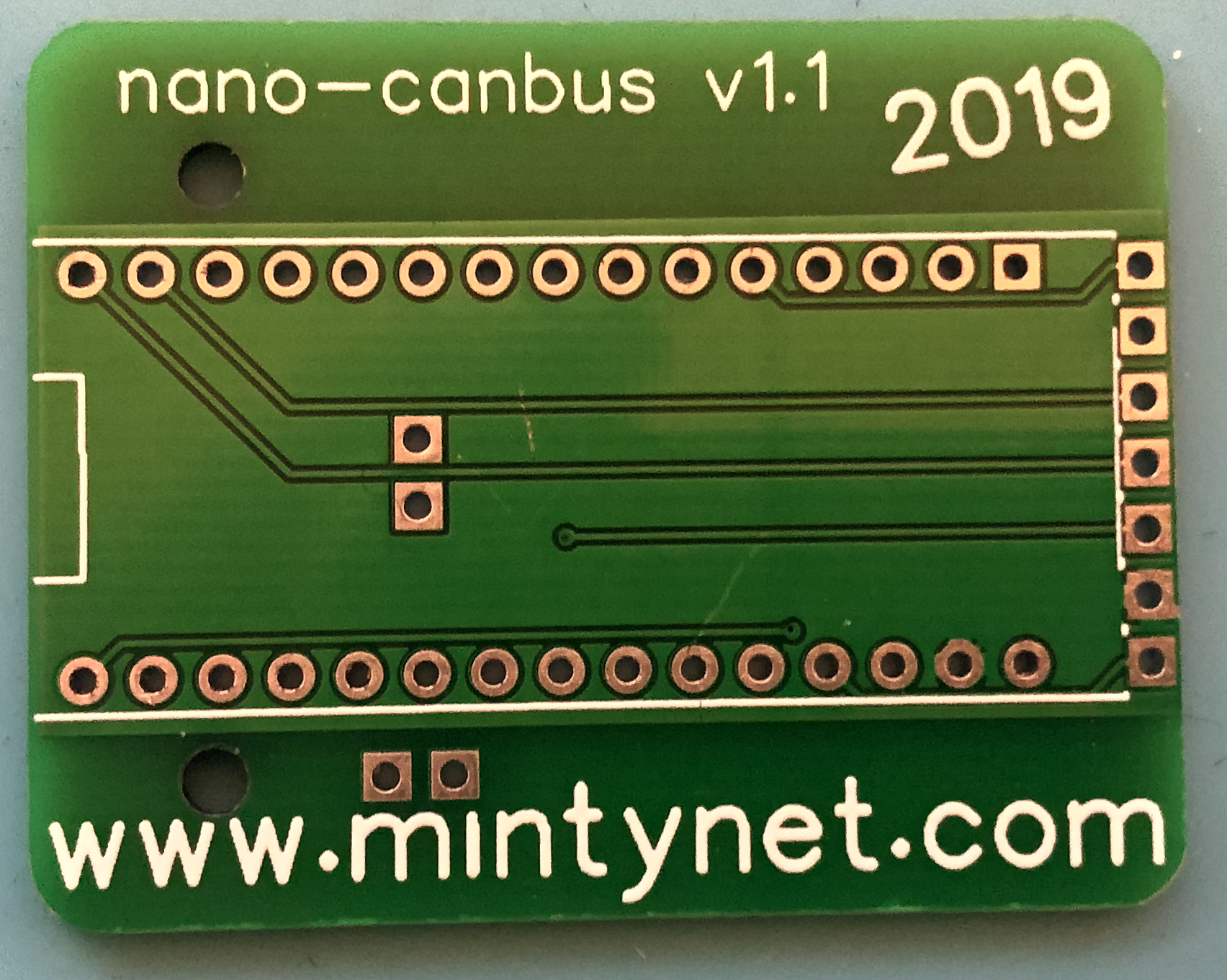
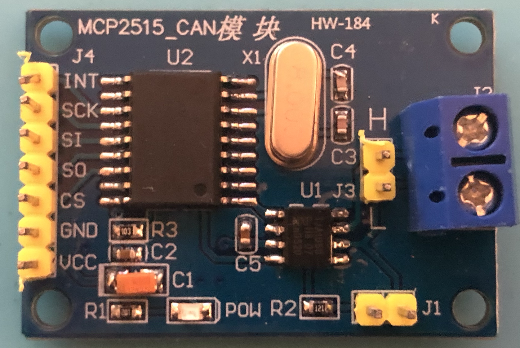
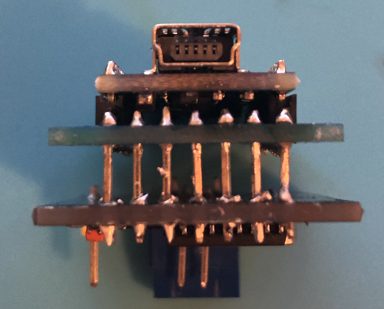
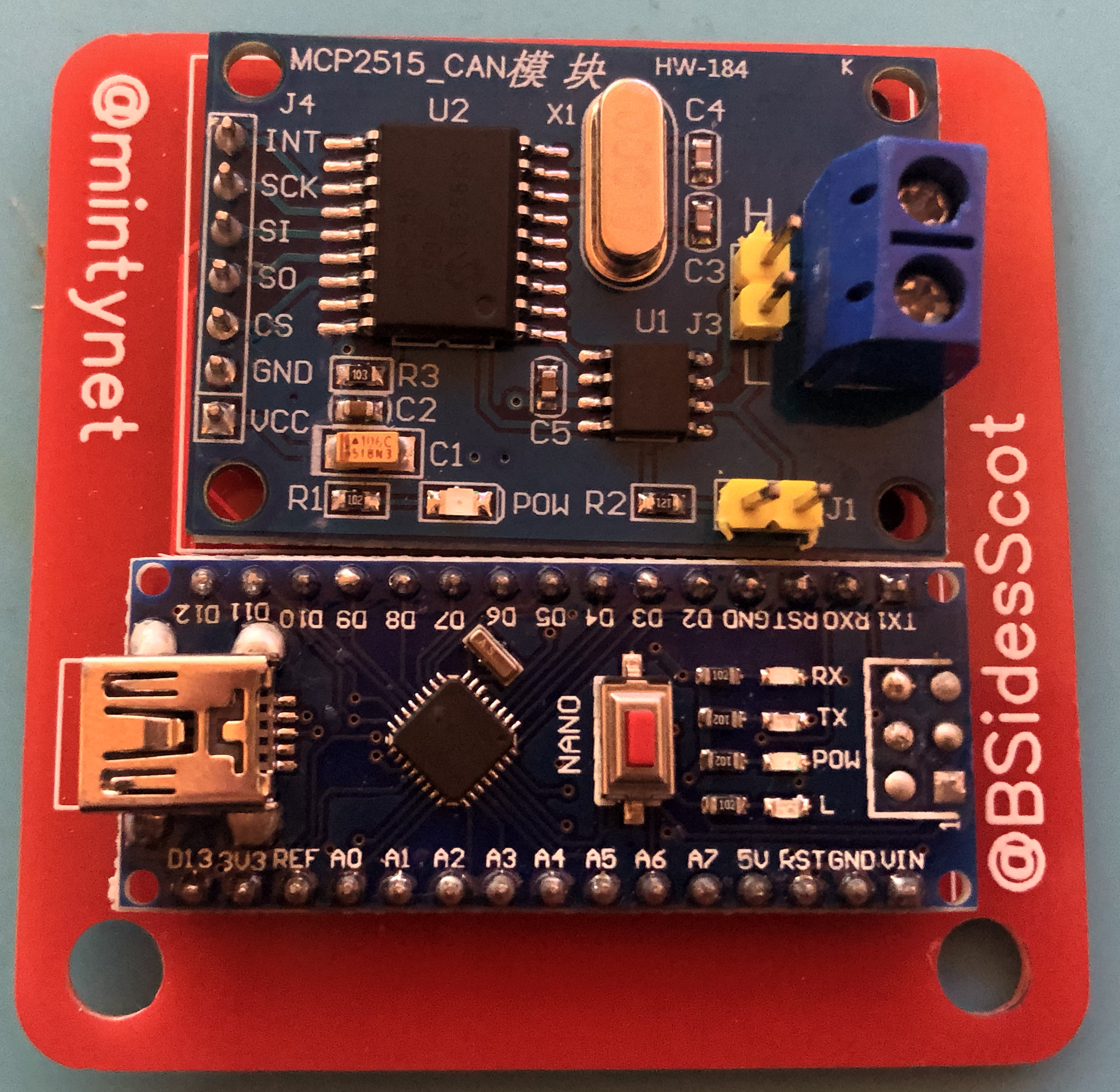
Firstly let’s start with identifying your PCB. If you attended the conference, you should still have the badge PCB. If you weren’t at the conference, or you’ve misplaced your badge, you may find that you’ve picked up one of Ian’s, or my, double sided PCBs. The only difference between them is the layout and the sizes, they all do exactly the same thing! If you couldn’t make it to the conference, you may have acquired one from BSides Leeds. Have a look at the images below, can you identify yours? If the answer is no, you may have a different make of CAN device, if so, this post won’t be covering how to use your device. However, keep an eye out! I’ll post something for you shortly!
If you’ve managed to find your PCB, in the images above and physically, let’s get started! Firstly, if you didn’t pick up the parts from Ian, you’ll need to source two components. These are an Arduino Nano and an MCP_2515 CAN Module. You can get these fairly cheap online from the likes of Aliexpress, or your favourite online Chinese wholesaler. I’ve added a couple of images to reference (below) so that you can be sure you’re buying the right parts! Don’t worry about clones, they all do the same thing. You may also want to pick up an OBDII connector. These can also be purchased from Aliexpress. However, they are not essential more of a luxury.
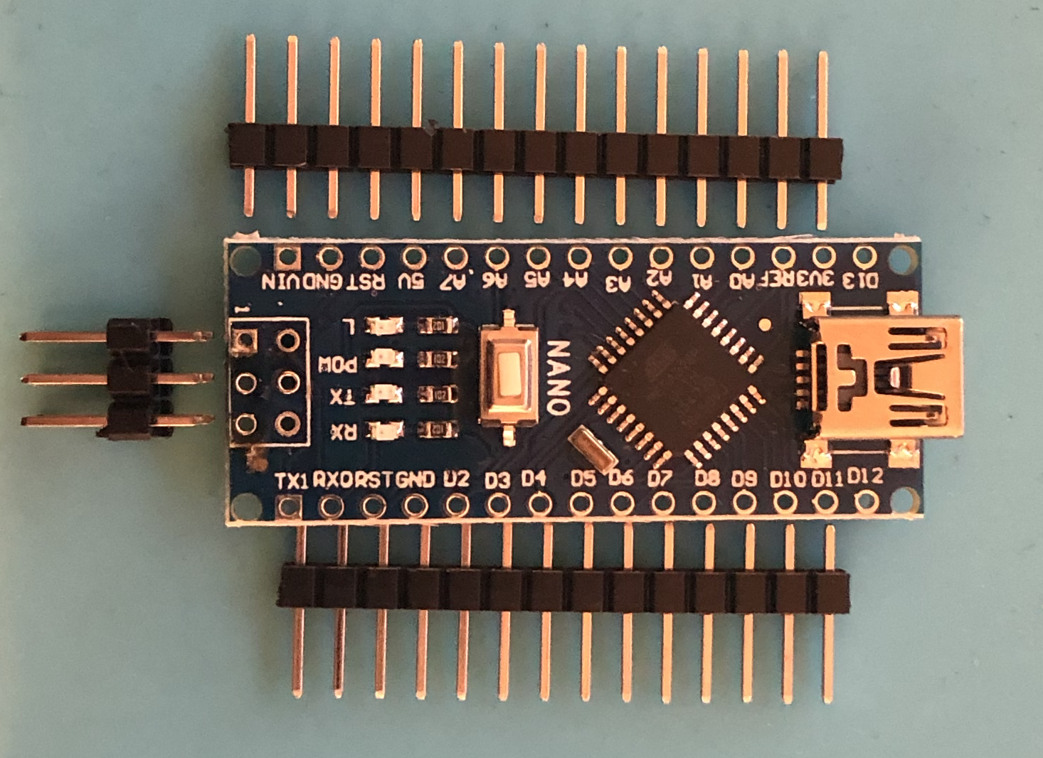
Once you receive your parts, we can start putting them together! For this stage, you’ll need a soldering iron and some solder. In reality, it’s only a small soldering job, so you shouldn’t need any fancy soldering kit. First, if your Arduino Nano has arrived un-soldered, such as the one pictured above, you’ll need to assemble it. Solder on the two single rows of headers, you can ignore the two by three headers. We won’t be needing them.
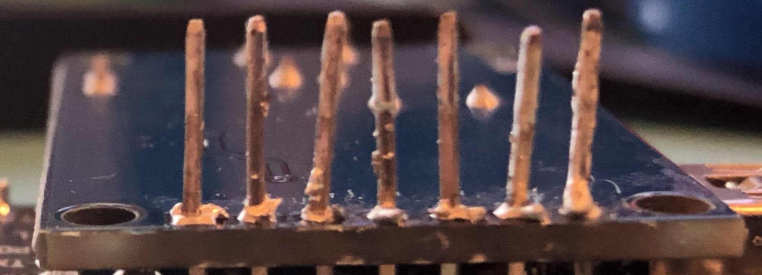
Now we can add this to our PCB. Regardless of which model you’re working with, there will be a small white square printed on the PCB. This may be a whole square or some may have been partially cut off. Either way, this is the side the mini-USB port wants to be on. Now that’s in place, go ahead and solder to the board from behind, making sure there are no pins bridged by solder. Once you’ve soldered that in place if you’re working with one of the back-to-back models, I’d recommend trimming the legs to just above the solder. If you’re working with a badge, feel free to do this as well although it’s not essential. It should end up looking like the image below.
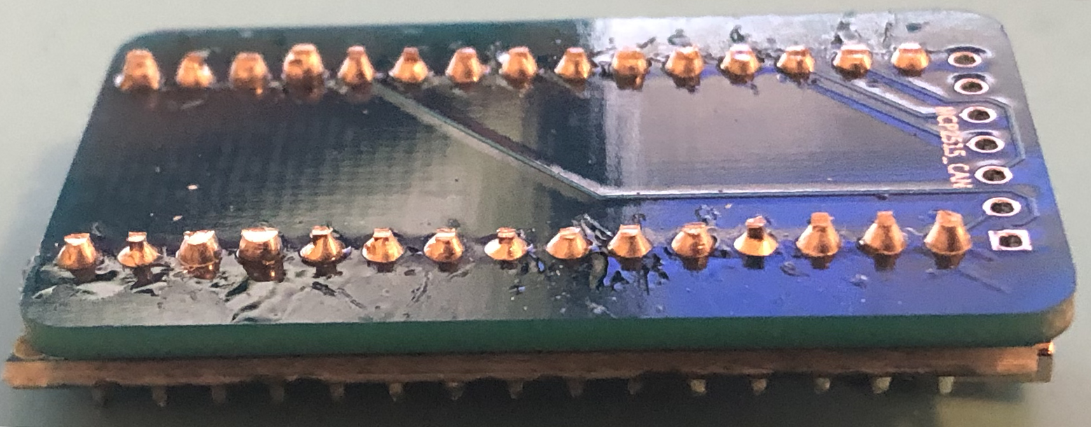
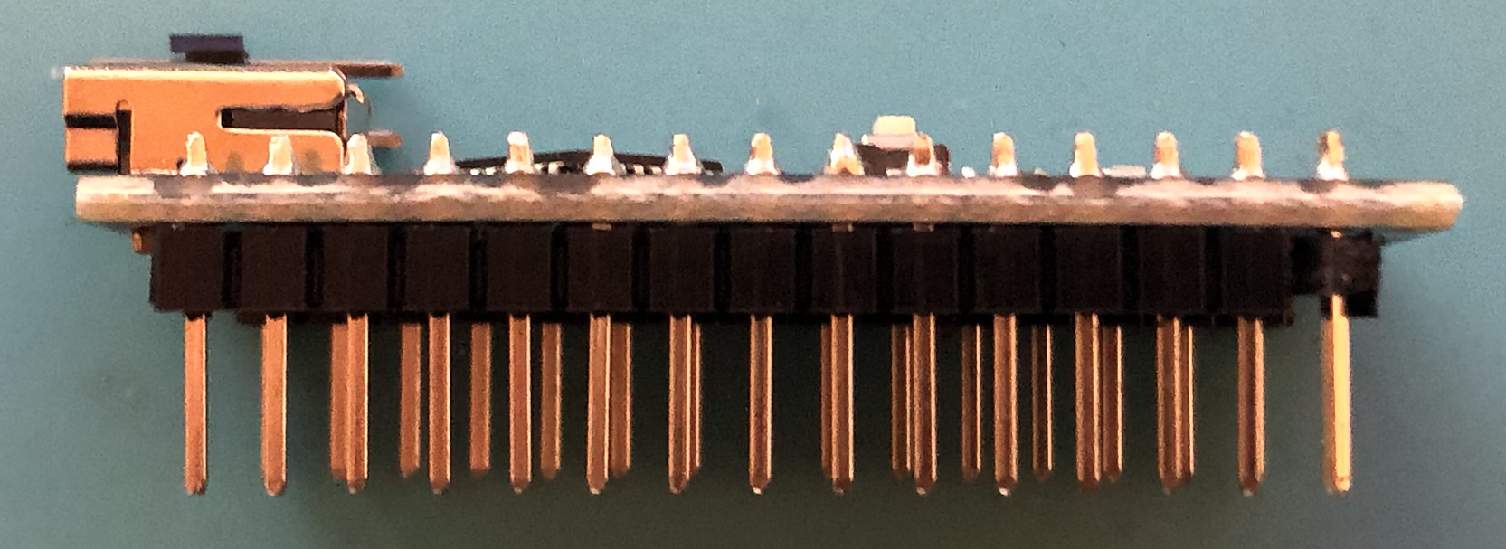
If you’ve trimmed the Arduino’s legs, you may want to run your soldering iron across the solder joints. This is purely aesthetic and just helps to give them a finished look. Anyway, next we’ll move on to the MCP2515 module. To start, you’ll want to remove the plastic from the header, depending on the manufacturer, this could be yellow. We want to end up with the headers on the reverse side of the board. How you do this is up to you. You may decide to remove the header and solder a new set on the reverse. I tend to push the pins through, one by one, by pushing against a desk whilst using the iron to liquify the solder. Either way, you’re looking to end up with something similar to the image below.
It may not look pretty, but we’ll fix that with the next stage of the build! Here you have two options you can either keep the headers at that length, giving you a large gap between the boards, or you can shorten the headers and add some electrical tape to Arduino solder joints, although not necessary it just provides an extra layer of shorting protection. Once you’ve decided how you wish to proceed, you’ll need to attach the MCP2515 to the PCB. You’ll likely find that the pins need straightening so that they’re aligned correctly. However, once done, go ahead and solder the two together. With that your Nano-CAN is complete!
You may want to add a little extra solder to the ground pads on the Arduino. Like in the image of the badge above. They tend to easily become loose… If you’ve decided you want to add an OBDII connector, we’ll add that now! Go ahead and solder a wire on both the contact for pin 6 (CAN High) and the contact for pin 14 (CAN Low). You may find that you need a multimeter to identify the correct contacts if they’re not labelled.
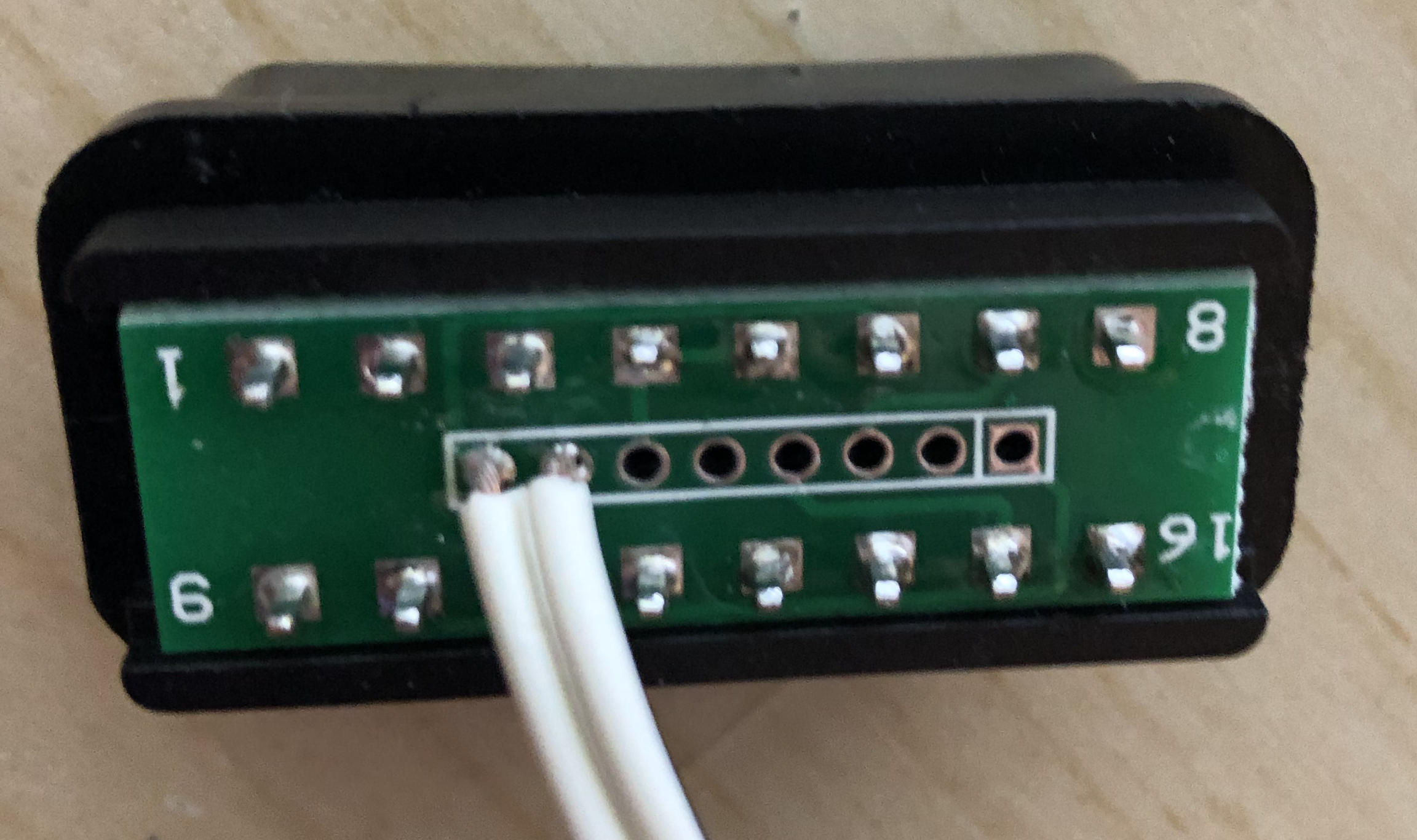
Once you’ve done that, you can reassemble the connector and attach the wires to the Nano-CAN via the screw terminal. Being sure to wire pin 14 to the side labelled ‘L’ and pin 6 to the side labelled ‘H’. With that, we’re ready to upload a sketch and get hacking!
First, head over to Ian’s (GitHub)[www.github.com/mintynet/nano-can] and download the Nano-CAN repo. In here you’ll find three sketches, one to read the CAN data, one to send CAN data, and one to display changing CAN data. For now, we’ll just be using the sketch which just reads CAN data, I don’t fancy dealing with broken cars just yet… Open the CAN-receive-all sketch in the Arduino IDE. Although these should be correctly set as default, we’ll just check a few options are set before we upload.
First, you’ll need to download and add to your library the MCP_CAN_lib, which is linked in the code. Next, check that the serial speed is set to 115200, on line 20. Then, check that the CAN bus speed is set to CAN_500KBPS and the crystal speed is set to MCP_8MHZ, on line 23.
As long as you’re accessing the bus via the OBDII port, you’ll not need to change the CAN bus speed. If you decide to go deeper into the car’s systems and access one of the other available busses you may need to lower the speed, but I’ll go more in-depth on that at a later date.
Now we can upload the sketch to our Nano-CAN. Start by connecting your Nano-CAN to your computer, via a mini-USB cable. Next, head to the tools menu and select your device under the port submenu. Then, make sure that the correct board is selected and click the upload button. This will compile the sketch, checking for any errors, then upload it to the board.

If you encounter an error during the upload process, I find that the most common cause is the processor selected. Head back into the tools menu, in the processor submenu try switching to the old bootloader. Then try uploading the sketch again.
Now it’s time to get our hack on! But first….
DISCLAIMER Please be aware that by following this guide, although unlikely, there is a chance of causing issues with your car. I take no responsibility for any issues caused!
Ok, now it’s time to get our hack on! First, you need a victim… I mean, willing test subject. If you’re not the owner of the vehicle you’ll be using be sure to get permission first! Once you’re in, you’ll need to locate the OBD port. The location of this will differ between models and makes. However, it will be easily accessible from the driver’s seat. Check under the dash, in the driver’s footwell, and around the centre console area. If you’re struggling a quick Google search should give you the answer.
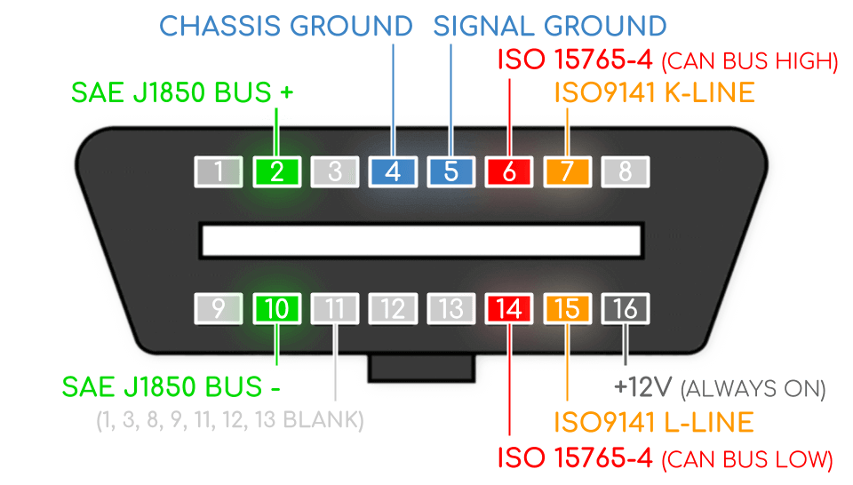
Once you’ve located your car’s OBD port, go ahead and connect the OBD plug on your Nano-CAN to it. If you chose not to purchase an OBDII connector, this will be a little trickier for you. Although not impossible! Take a look at the pin out of the OBDII connector below. What you’ll want to do is find a small piece of stiff metal, such as a pin or a paperclip. You could also use some stiff solid core wire, this would allow you to connect it straight to the screw terminal on the MCP2515. Take these and insert them into pins 6 and 14, the red coded pins in the pin out. Then connect those to the high and low on the MCP2515. Pin 6 being high and pin 14 being low.
Once you’ve done this, you’ve got the option of using either the serial monitor in the Arduino IDE or an alternative serial console. In this post, I’ll be using Screen, feel free to use whichever you’re most comfortable with. First, you’ll need to identify which port your Nano-CAN is using. There are a few ways to do this but I find the easiest is to check in the Arduino IDE, in the tools menu within the port submenu. Next, open a terminal window and run screen </dev/ttyUSB0> 115200 replace the <> with your port. This will open a serial connection with the Nano-CAN at a speed of 115200, which was defined in our sketch. Finally, once you see a configuration successful message, it’s time to turn the car’s ignition to the on position. This provides power to the vehicle without starting the engine. If you don’t see a configuration successful message try rebooting your Arduino Nano, using the small button on top. You should now find that data starts flying onto the screen, such as below.
You’ll likely find that the data comes through much quicker than in the animation above. This is purely due to the fact that it was raining at the time of me writing this, so I generated the data instead of getting wet… I’ll cover that in another post! Anyway, once you’ve finished watching your data, you can write the data to a log file (Ctrl + a, then type :log on), or just quit with Ctrl + a, then :quit .
And with that, we’re done! I hope you’ve managed to get your first glimpse of CAN data if not feel free to shoot me a DM @_GarethP and I’ll help where I can! Otherwise, I’ll look to cover what you can do with this data and how you can identify messages in my next post. In the meantime, I’d recommend having a read of Craig Smith’s Car Hacker’s Handbook. It’s available to purchase from Amazon, or can be downloaded as a PDF from opengarages.